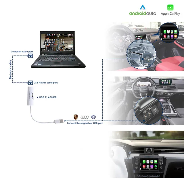
1st Access Porsche PCM5.0 MH2p Engineering Menu
2nd set up the IP address
3rd windows +R, CMD ping 172.16.250.248
If you want to know more about Porsche, please click Porsche Trouble Repair.
1st Access Porsche PCM5.0 MH2p Engineering Menu
2nd set up the IP address
3rd windows +R, CMD ping 172.16.250.248
If you want to know more about Porsche, please click Porsche Trouble Repair.
What is BMW Rheingold ISTA ?
ISTA is a workshop system that contains BMW AG Data and Information. ISTA stands for Integrated Service Technical Application. Way back when, during the initial development of this tool, BMW used DIS (Diagnostics Information System), and as the programs evolved and due to the nature of the file naming conventions utilized by BMW, the workshop system became known as Rheingold in the enthusiast world. Rheingold in actuality is the folder that contains the main application and data. Rheingold became ISTA-D (D stands for Diagnostics) and BMW’s programming application (not discussed in this document) used the same nomenclature, ISTA except with a P (for programming) or ISTA-P.
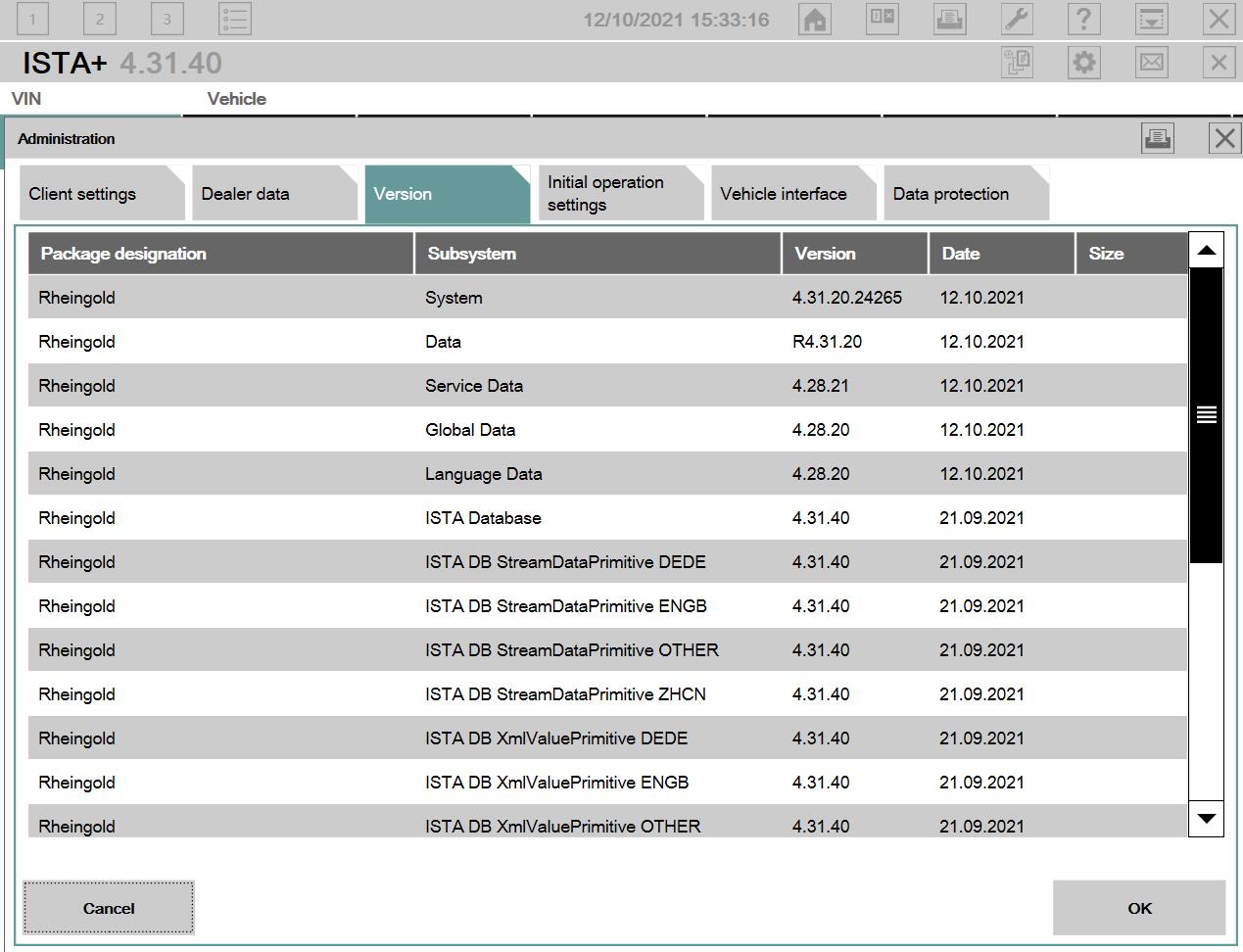
This instruction show you guide on how to configure BMW ISTA 4.28.xx software with new Firmware BMW_ISPI_ICOM-FW_03-15-04.msi for ICOM A1 & A2.
Requires:
BMW Rheingold ISTA+ 4.31.40 4.23.14 &ISTA-P Free download
Config Manual for ISTA 4.28.xx & BMW Standard tools
1.ICOM A1, A2, BMW ICOM update firmware to BMW_ISPI_ICOM-FW_03-15-04.msi
2.Log in to ICOM http://169.254.92.38:58000/
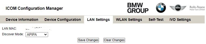
3.Go to LAN Setting and set Discover Mode to APIPA Save Changes and reboot ICOM.
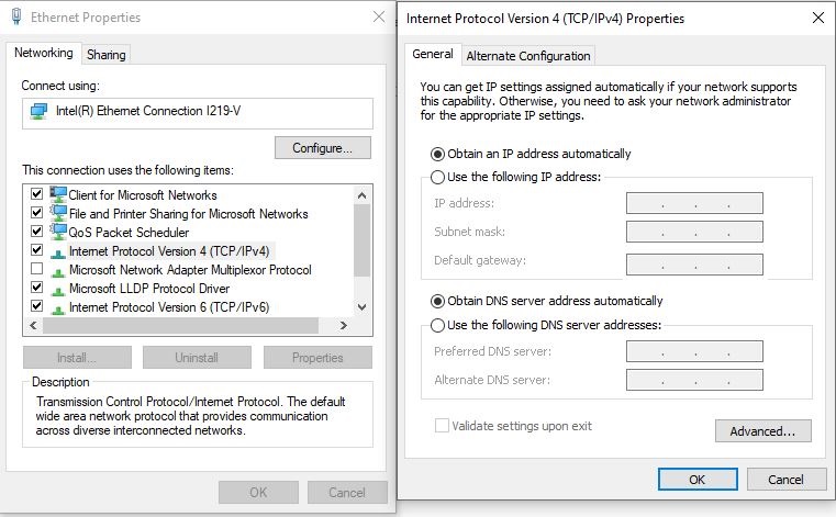
4.On your Laptop go to Ethernet Properties and set (TCP/IPv4) to DHCP.
Connect your laptop and ICOM with Ethernet cable.
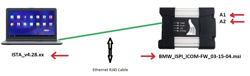
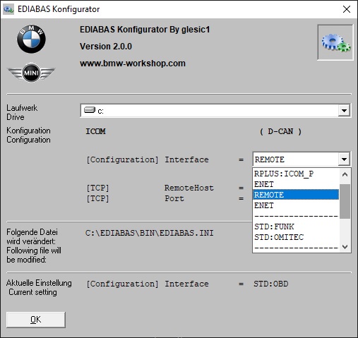
5.Open ediabas konfigurator2.0.0
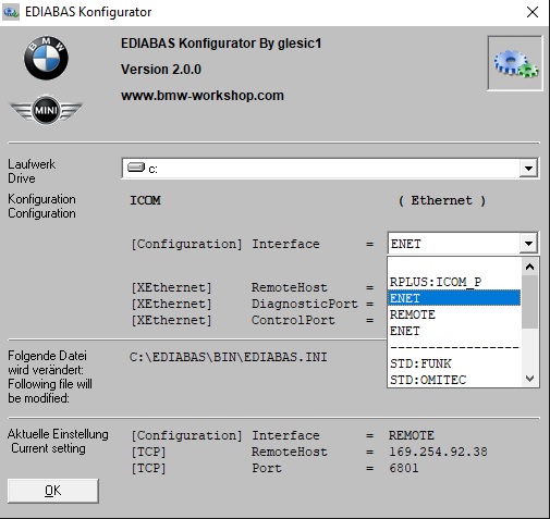
Select ICOM (Ethernet) This will be used with ISTA 4.28.x.x For BMW Standard Tools check setting below. Under BMW Standard Tools Config
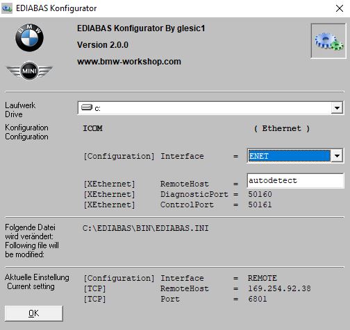
Click on OK
6.Open ISTA 4.28.xx and set Vehicle Interface to see below.
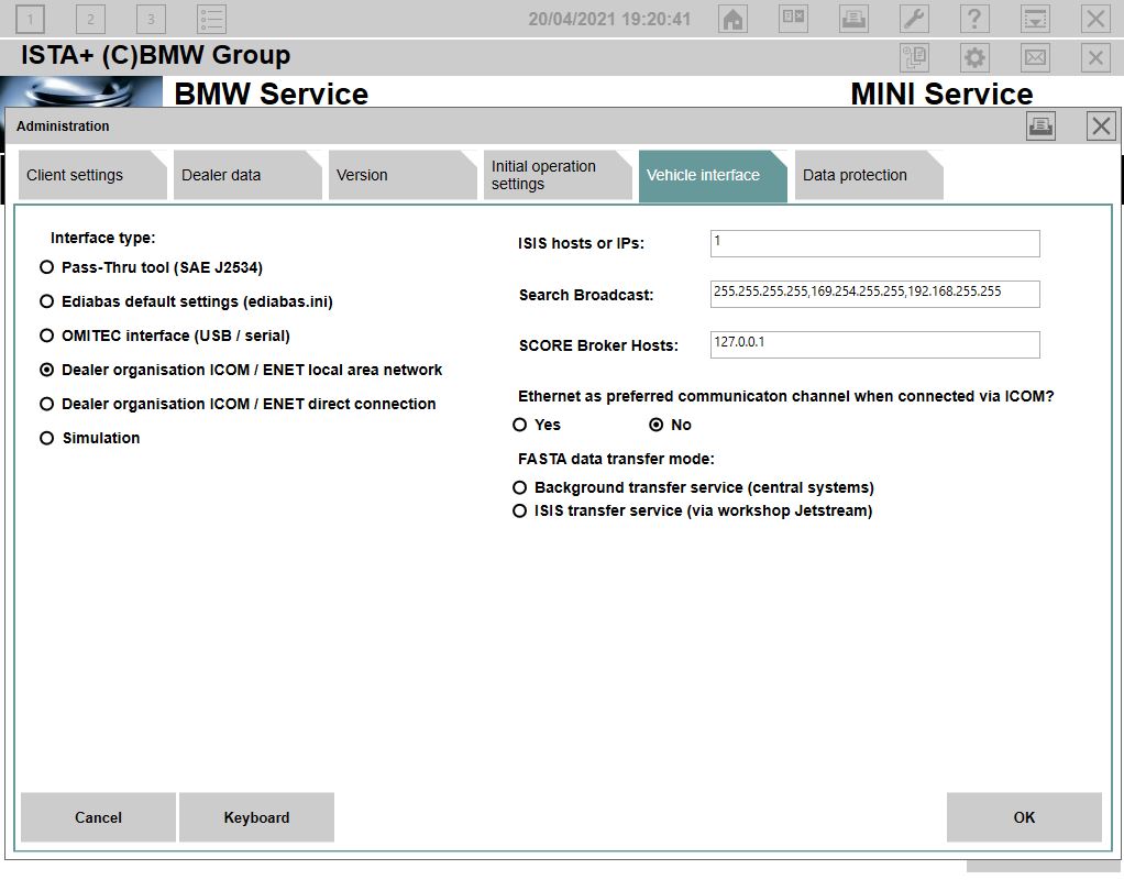
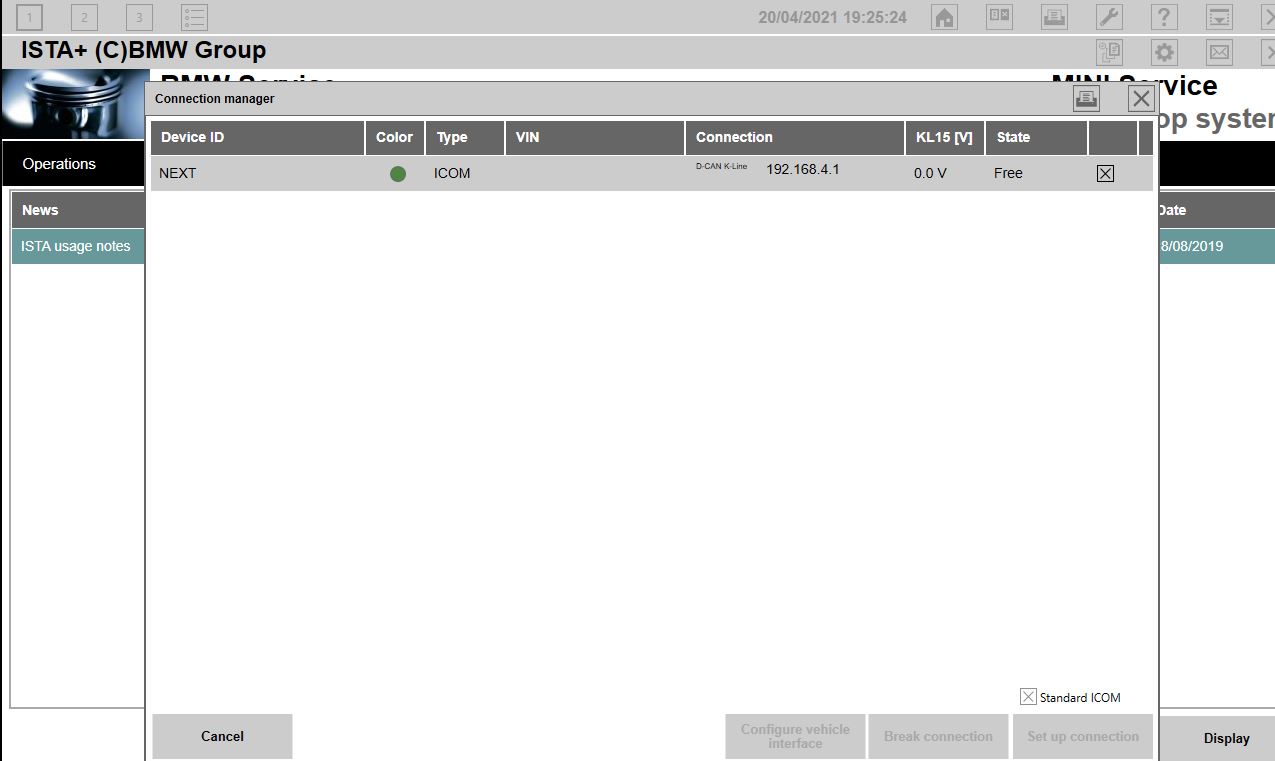
7.You Can now connect to your car E – F – G series. See that you ip has changed to 192.168.x.x This will not happening with INPA……
BMW Standard Tools Config
After you have configured everything for ISTA 4.28.xx and everything works as described above. You only need to set the (Configuration) Interface = to Remote as indicated below. EDIABAS will connect with IP 169.254.92.38
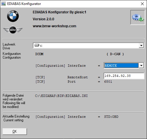
This will be used for BMW Standard Tools
You can now connect with ITool Radar or Easy connect, and use INPA, NCS-Expert Tool, Tool32, WinKFP.
What is Caterpillar ET?
Caterpillar Electronic Technician (Cat ET) is diagnostic software required to communicate, diagnose and service electronically controlled Caterpillar engines and machines. When connected to an Electronic Control Module (ECM), a technician has the ability to diagnose existing and potential problems, configure the product, and obtain data for analysis.
Caterpillar ET Functions List:
1.View active and logged diagnostics.
2.View events where irregularities occurred and were logged by the ECM.
3.View the status of a group of parameters (temperatures, pressures, etc.) simultaneously.
4.Record and log performance data.
5.Graph a group of status parameters.
6.View the current configuration of an ECM.
7.Change ECM configurations.
8.Perform diagnostic tests.
9.Perform calibrations.
10.Print reports and diagnostic results.
11.Please keep in mind that some ecm settings for example, speed limit requires factory password. The factory password generator is not included in this application
Caterpillar ET Support Languages:
English,Chinese,Danish,French,German,Italian,Portuguese,Spanish
Caterpillar ET Support OS:
Window 7,Window 8,8.1,Window 10 32 bit and 64 bit
PC Requirements
Recommended Configurations
PC containing a 2.0 GHz dual-core processor·
3GB RAM·
3GB of available hard disk drive·
DVD-ROM drive·
15.4 inch XGA Screen (1280×1024 compatible)·
MicrosoftÒWindows™ 7 Professionalor Windows 8 Professional
(Note: Windows 8 RT is not supported)·
RS232 port with 16550AF UART or compatible (for use with Comm Adapter II)·
USB 1.1 or 2.0 port (for use with Comm Adapter 3)·
Ethernet RJ45 connector·
Built in pointing device or mouse·
For security purposes, MicrosoftÒInternet Explorerversion 9 or newer is recommended.
Note: The most recent version of MicrosoftÒInternet Explorer may not be validated to work with the service tool.
Minimum Configurations
PC containing a Pentium 2 GHz processor or greater·
1GB RAM·
500MB of available hard disk drive·
CD-ROM drive·
Super VGA monitor or display (1024×768)·
MicrosoftÒWindows™ 7 Professional or Windows 8 Professional
(Note: Windows 8 RT is not supported)·
RS232 port with 16550AF UART or compatible (for use with Comm Adapter II)·
USB 1.1 or 2.0 port (for use with Comm Adapter 3)·
Ethernet RJ45 connector·
Built in pointing device or mouse·
For security purposes, MicrosoftÒInternet Explorer version 9 or newer is recommended.
Note: The most recent version of MicrosoftÒInternet Explorer may not be validated to work with the service tool.
Caterpillar ET Free Download
Caterpillar ET 2018 A
https://mega.nz/#!zIZUDARZ!q8wQWzgM9CeZrxZdp5VhaFCRULvv_b_ENE0e1Oe_UHM
Caterpillar ET 2021B & 2019C Download (paid version work 100%)
https://www.obd2tool.com/goods-10220-Cat-Caterpillar-ET-Cat-ET-3-Software.html
We will install the software before the shipment , so you can get it work directly after you receive it.
Software is Updated to 2015.09 for car
Software is Updated to 2012.09 for truck
Supported Languages: English, Spanish, French, Italian, Turkiah, Greek, German, Czech, Polish, Russian
Memory Card
Stores data for ECU reprogramming, drive recorder, etc.
This is a standard, off-the-shelf memory card. The one provided (with
reprogramming data) is a Compact Flash memory card (MB991853)
inserted into the CF card adapter (MB991939).
Features:
1. Color Display.
2. Fast vehicle scan.
3. Can perform drive recorder on most Mit-subishi vehicles.
4. Data Display utilizes either graphical or digital display.
Product Description:
In accordance with releasing new products that introduce CAN
communications systems, MMC has developed the MUT-III as a next
generation diagnosis tester for servicing these new and future vehicles.
A personal computer (PC) is connected to the MUTIII unit and used as a system’s control terminal, and communicates with a vehicle ECU through the VCI. In addition to being able to handle all diagnosis functions covered by the conventional MUT-II tester, the MUT-III system can display data as easy-to-understand diagrams and graphs on a large screen of the PC. Unlike the MUT-II, the MUT-III can retain data on all vehicles, from old to new models, classified according to destination in the PC’s hard disk. This eliminates the awkward but essential job with the MUT-II, of switching the data list (communications protocol data and diagnosis item list database) by replacing the ROM pack with another according to the vehicle model and year model.
New functions that make use of the advantages of the PC are also being developed. For example, the workshop manual viewer is a useful function for mechanics as they no longer have to carry around a thick manual and search for relevant pages while working on a vehicle. The workshop manual viewer is currently available for certain vehicle models, and allows users to retrieve the pages containing the failure code for a particular problem at the push of a button.
Set Includes:
1. Vehicle Communication Interface (V. C. I. ) (MB991824)
A communication interface used to connect the vehicle ECUs and the PC.
1). When connected with the PC
– Vehicle diagnosis (Interactive fault diagnosis)
– SWS communication; CAN communication support
– Drive recorder
– ECU reprogramming
– Volt, Ohm, measurement
– Fuel pressure measurement (Not available in US)
2). When used with the V. C. I. Unit (disconnected from PC)
– V. C. I. Stand-alone diagnosis
– Drive recorder
– ECU reprogramming
– Volt, Ohm measurement
– Belt Tension measurement
(MB991939).
2. MUT-III Main Harness A (MB991910)
Used when connecting the V. C. I. with vehicles that have
Only one 16-pin diagnosis connector.
– Supports fault diagnosis and ECU updating on the
Above-described vehicles
– Supports the CAN communication system
3. MUT -III Main Harness B (MB991911)
Used when connecting V. C. I. with vehicles that have a 16-pin + 12-pin or 16-pin + 13-pin diagnosis connector.
For models equipped with only 12-pin (or 12-pin + 12-pin) Diagnosis
connector, connect the M. U. T. -II adapter harness (MB991498)
to the end of this harness in the same as M. U. T. -II, and power is supplied from the cigarette lighter Socket.
Package List:
1. Carrying case
2. Vehicle Communication Interface (VCI).
3. 2pcs 16pin Adapter
4. USB 2.0 cable.
5. Harness 1 (yellow,1-2).for old cars
6. Harness 2 (red, 1-3).for old cars
7. Harness 3 (blue).for new cars
8. Harness 4 with lighter (1-4) for trucks
9. Harness 5 (black) for trucks
10.1pcs memory card
11.1pc x Second Hand Laptop Lenovo X220 laptop with software
Second Hand Laptop Lenovo X220 Laptop with V2021.10 software:
Brand: Lenovo
Condition: Used
Type:Laptop/Notebook
Screen Size:12.0
Processor Type:Intel (R) Core(TM) I5-2520M CPU
Processor Speed:2.50 GHz
Memory: 4GB
An item that has been used previously. The item may have some signs of
cosmetic wear, but is fully operational and functions as intended.
Primary Drive: DVD+/-RW Processor Speed: 2.53GHz
Processor Configuration: Dual Core
Question:
Q1: Is this for chevy volt 2012 to reprogram the hybrid system ecu unit is it going to work?
Solution: This item is without a program software, just hardware support. If you have it, you can implement software the program
Q2: I got the software I installed the hard drive tell me how to use it which software open first what are the steps
Solution:
1). Please insert the HDD into the computer
2). The boot display is Windows 7 and the GDS 2 needs to be opened. And then it is ok for diagnosis.
Q3: I open GDS2 ans no lease found. Do I have to connect to the internet or not how to fix the lease not found?
Solution: Our engineer will help you check it remotely.
Q4: Which package do I have to install. Gm China or gm global?
Solution: Don’t install anything. If do, it won’t work. Just choose your car type and use it
Q5:
Solution:
1)May I know if the tool is connected your car? If not, please connect your car.
2)To make sure GM MDI 2 working
3)Please try to change another USB port
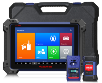
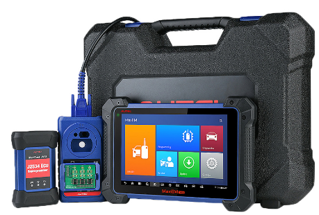
Here introduce the Autel IM608 Pro Key programmer. Hope this article can work for you .
Recently So many friends asked what is different between Autel MaxiIM IM608 and Autel MaxiIM IM608 PRO.
In
fact there is no big different between both.The main different is IM608
PRO with the XP400 Pro Key Programmer ,but if you you have the Autel
MaxiIM IM608 ,You can just purchase XP400 Pro separately to do same
function as IM608 PRO.
Autel MaxiIM IM608 PRO Highlights:
1. Upgraded Version of Autel IM608 Key Programmer
2. One Year Free Update Online on Autel Official Website
3. Comes with XP400 Pro which adds more functionality for BMW, Mercedes-Benz, as well as EEPROM reading
4. Used with IMKPA Accessories Which adds BMW EWS3 key learning, Benz NEC key learning and Benz ESL_W209 read/write/erase
5. Existing Autel IM508/ IM608 Users Can Upgrade To IM608 Pro by Purchasing XP400 Pro Programmer
Autel MaxiIM IM608 Functions:
1.Read & Clear Fault Codes | Short description & code provided (can clear faults & warning lights)
2. Service Functions | Oil light / EPB / BMS / SAS / DAF etc
3.Access Live Data | Data from the ECU/Modulesnsors displayed in real-time (Oxygen sensor-rich/lean etc)
4.Actuation/Component Testing | Actuate (switch on/off) to diagnose functionality (relays, fans, locks etc)
5.Coding Functions | Allows you to change vehicle parts that need to be “coded” (Injectors, ABS, starters etc)
6.Flashing/ Reprogramming | Advanced updating/coding of ECU’s online through a J2534 pass-through flashing device
7.Advanced Key Programming | IMMO functions, Transponder read/write/identify, MCU/EEPROM chip read/write
If
you want to learn more about IM608 or IM608 PRO .You can search on our
store :www.obdii.shop ,or email to us :sales@obd2tool.com .
My Chevy Volt was manufactured in late 2011, but it is a MY2012 with a Denso navigation head unit. I purchase a new 22925286 unit (option codes UFU & UP9) at $35 and works totally fine after reprogramming through my VXDIAG VCX Nano GM GDS2 with a $40 SPS subscription.
An SPS subscription will only let you program the correct model & model year vehicle for the VIN you provided in TIS2Web. So selecting a different model year likely will still keep you blocked from programming one way or another. Programming process in SPS may be different for 2011 Volts. You need try by yourself.
Here’s a set of screenshots showing what the reprogramming/swapping process was like for me. Hope it helps.
Swap Denso HDD with Navi and Bose on the Volt 12′:
– You need to find a head unit with a part number 22925286. PRO code for
the unit with NAVI is &UFU&UP9. Bose is just software stuff
which needs to be activated during reprogramming.
(click to enlarge images)

GDS2 ID information before reprogramming
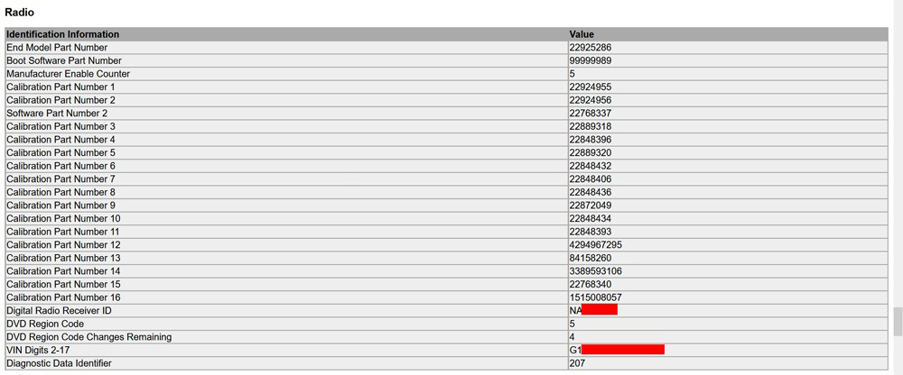
Radio ID information pinout from GDS2, post-reprogramming
The second screenshot is just a printout from one of GDS2’s menus, nothing too different from the first screenshot aside from its formatting.
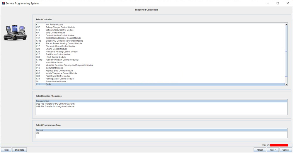
Select Radio module and Programming
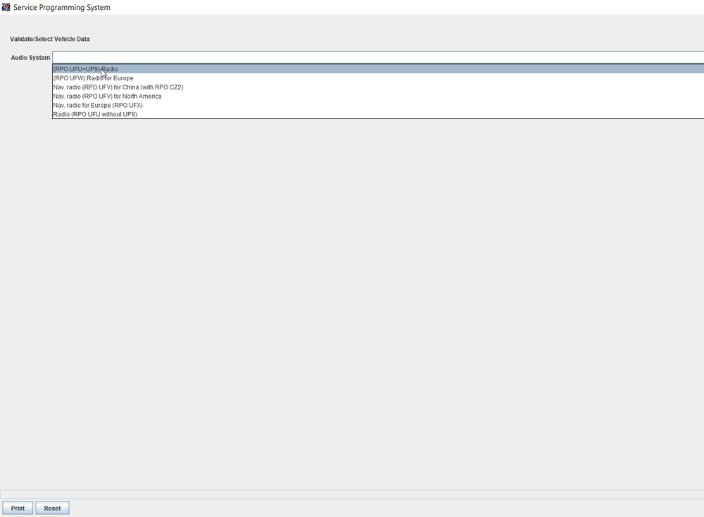
Audio system selection screen, UFU+UP9 were the options my factory radio had.
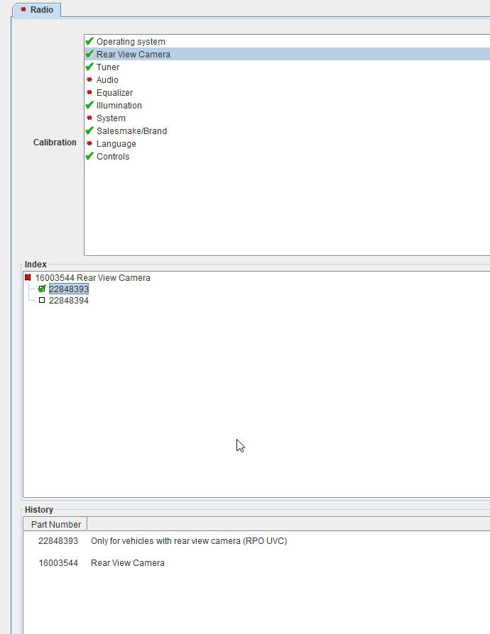
Rear view Camera option selection. Pretty self-explanatory, does your car have a backup camera or no?
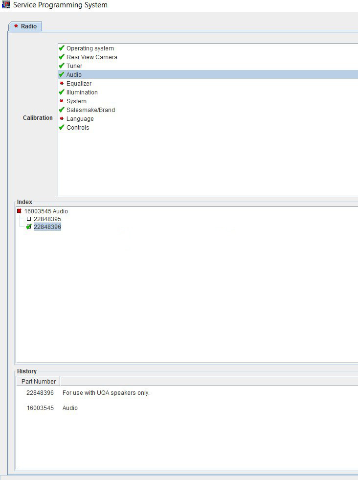
Audio and Equalizer options will setup the radio according to whether your car has the Bose system (UQA) or not (UZ6)
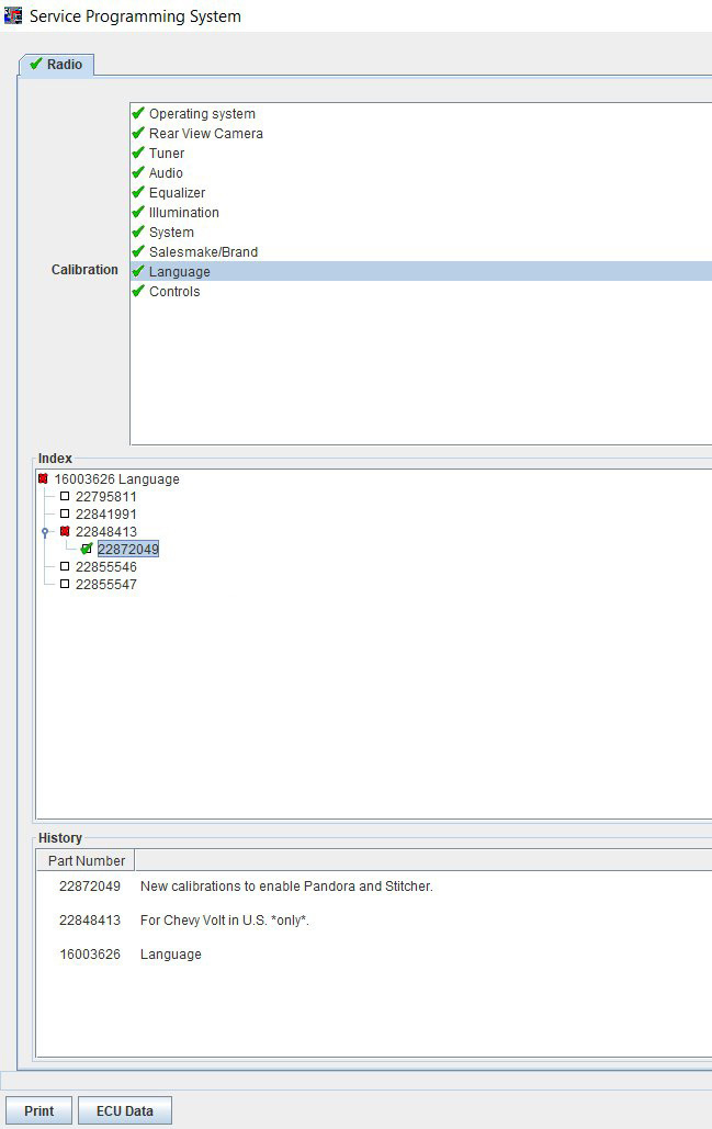
Language calibrations are similar easy enough. In this case i selected the U.S only calibration.
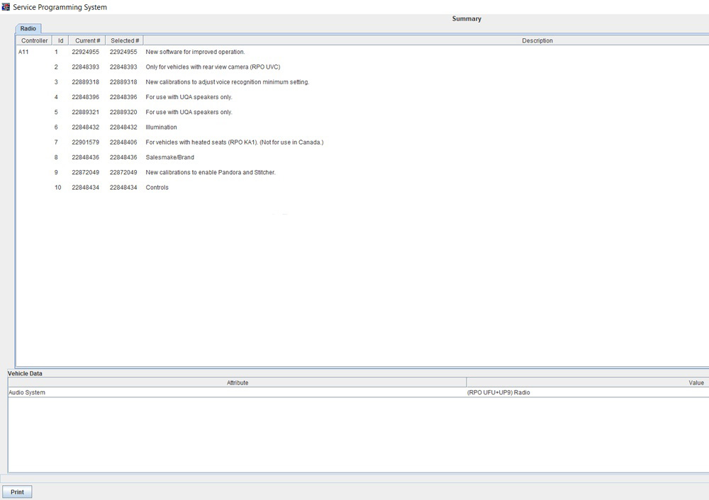
This is the last screen you’ll see before programming. It will confirm whether you are actuvally makeing any changes or not. I messed up my option codes when programming for the first time, so i’m actually glad i went and did this.
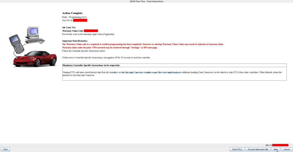
Done. Reprogramming the new calibrations only took a few seconds. Then clear existing DTCs.
JCB Electronic Service Tool Heavy truck scanner comes with JCB Service Master 4 V1.73.3 software in CD, supports multi language. JCB Service Master is a gateway application allowing a large number of Vehicle Support Applications to be linked using one familiar interface.
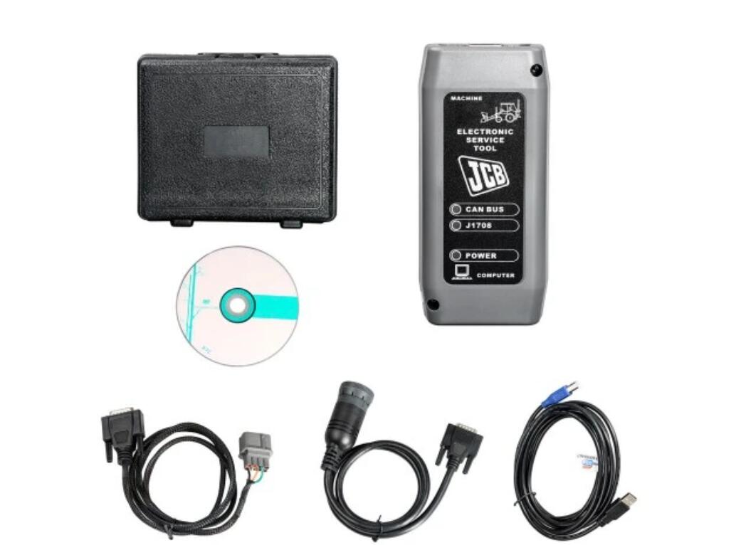
JCB Electronic Service Tool Description
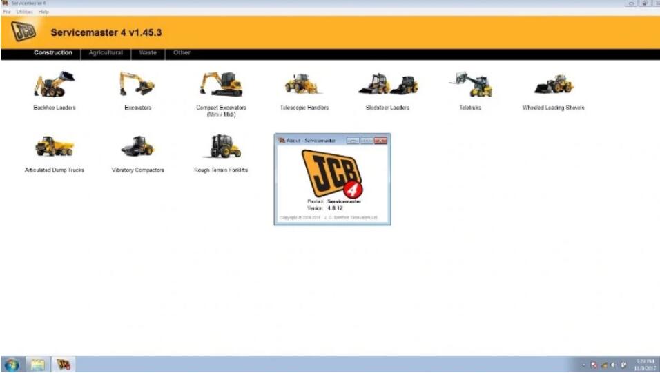
1. JCB Service Master is a gateway application allowing a large number
of Vehicle Support Applications to be linked using one familiar
interface.
2. The interface acts as a graphical tool for selecting the target
vehicle from a groups of Vehicle Families and triggering the particular
Service Tool Application desired. This removes the need for a user to
‘remember’ every individual service tool available and select which one
if intended for a particular machine.
3. The JCB Service Master also provides several key features that will
accompany all JCB projects, a multi language editing tool that provides a
means of individual text string translation for all JCB applications
and a means to select a localized language translation for the each JCB
application.
JCB Electronic Service Tool Highlights:
1. Reads fault codes and ranks them in order of importance.
2. Calibrates, parameterize ECM and program blocks.
3. Conducts dropping service intervals.
4. Compatible with software JCB Service Master 4 (2019).
5. It works with CAN protocol in OBD II system.
6. It is provided with instructions for use, repair and diagnostics of vehicles JCB engines and Isuzu, Deutz, Cummins.
7. Full original JCB repair and service manuals and bulletins
8. JCB spare parts for all markets
9. Programming special parameters (order separately)
10. Supported languages: English, German, Spanish, French, Italian, Portuguese.
JCB Electronic Service Tool Supported Models and Engines:
JS Range, JZ70, BackHoe Loader, Loadall 2007-, Loadall 2007+, Robot, Teletruk, Midi Excavator, Dump Truck, Fastrac 2000-3000 Series, Fastrac 8250 Series 1, Fastrac 8250 Series 2, Fastrac 7000 Series 1, Large Wheel Loading Shovels, Vibromax, JCB Dieselmax Engine, JCB Engine (IPU OEM), JCB Engine (Base Engine OEM), JCB Generators, LiveLink.
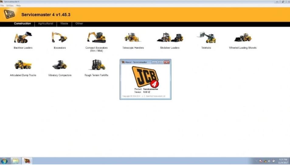
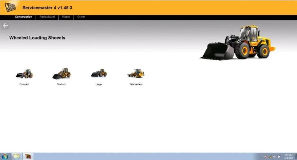
JCB Electronic Service Tool Software Display
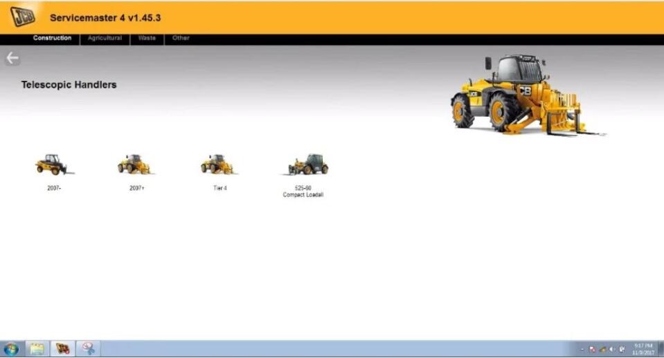
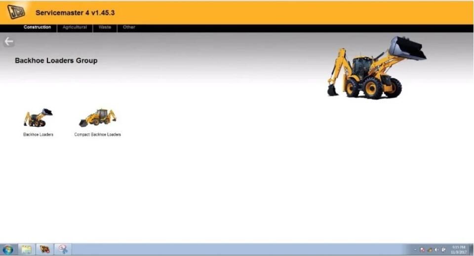
Packing List
1 x JCB Electronic Service Tool Diagnostic Interface
1 x 9 Pin and 6Pin Cable
1 x USB Cable
1 x JCB Service Master Diagnostic Software CD
END.
This is a basic guide on how to use NCS Expert. I won’t cover the complete list of codable options, because frankly there’s far too many. In the next post I’ve attached a copy of Obioban’s coding thread from the original m3forum. This guide will be focused on the E46. Coding other cars is similar, but some modules will be different etc.
Requirements:
* A working Ediabas installation and appropriate interface (see Intro to BMW Coding / Diagnosis and setting Ediabas)
* An NCS Expert Profile with manipulation enabled – I’ve attached the
one I personally use to this post (requires NCS Expert V4 – included
with the BMW Standard Tools 2.12 mentioned in the setup thread). Copy
the profile to C:\NCSEXPER\PFL
* NCS Dummy (not technically required for coding, but this guide will assume you have it and are using it).
Starting NCS Expert and Reading the Vehicle Order / ZCS
* Open NCS Expert, click File -> Load Profile and choose “Expert Mode w/ Manipulation”
* Click on ZCS/FA f. ECU and select the appropriate chassis
* In the E46 you’ll see 4 different options: AKMB, ALSZ, EWS, and KMB
* * If your car is built in 09/2001 or later, you’ll want to pick
AKMB or ALSZ (both should have the same options stored unless your car
has been messed with in the past).
* * If your car was built earlier, pick EWS or KMB
* You’ll now see your VIN by FG (It might just be the last 7 digits that are correct, that is OK).
* If your car is built 09/2002 or later you’ll see a field labeled
“FA” with a long string. You will sometimes see the “FA” referred to as a
“VO” or “Vehicle Order” – these are interchangeable terms. If your car
was built earlier, you’ll see 3 different entries (GM, SA, VN) with
hexadecimal strings afterwards. The GM, SA, and VN together are
collectively known as a ZCS.
* * The VO and ZCS are basically a list of options and official
retrofits your car has. These are stored in 2 separate modules on the
car. These strings tell the coding software how to code your car. They
do not directly impact the code itself (i.e. changing the VO/ZCS without
also coding modules will not actually change how your car functions).
* * We will discuss VO/ZCS changes later.
Simple Coding:
Let’s start with simple coding. Let us say for example you want to be able to close your windows via remote.
* First hit “back” on NCS Expert and now you will see a button labeled “Process ECU”, click that.
* You’ll now see the list of modules your car should have. In this
case, the option we’re interested in is stored in the GM5 module, so
select that.
* Now click on the “Reading ECU” button. NCS Expert will now read the
configuration from your GM5 module. You may see a notepad window open up
with a bunch of parameters – close that.
* AFTER reading the module, make note of the version of the GM5
module. In the example below, you’ll note mine says GM5.C06. Your car’s
module version will vary depending on the age of the car, whether the
module was ever replaced, etc.
* Now open NCS Dummy. Select E46 as your chassis. Under module select
the appropriate module (in my case, GM5.C06 as discussed above). Now by
“FSW/PSW or Netttodat trace” click Browse. This should automatically
point to NCS Expert’s WORK folder. You should see a file labeled
“FSW_PSW.TRC”, select that
* So in the case of this option, I know the parameter we’re looking
for is called “KOMFORTSCHLIESSUNG_FB” – so use the search function in
NCS Dummy and search for that parameter.
* You will find that it defaults to “nicht_aktiv”. Click on the
checkbox for “aktiv”, and then click “Export FSW_PSW” and within that
menu select “Export FSW_PSW.MAN”
* Now go back to NCS Expert. Click on “Change Job” and select “SG_CODIEREN”.
* Now click Execute Job. Wait a few seconds, and it should say “Coding Ended”.
Congratulations, if all went well, you’ve successfully coded your car.
Enabling/disabling other features follows the same basic process. The module you have to edit, the name of the parameters, the number of parameters, etc will vary, but if you can follow the above steps, you can probably figure out how to follow other DIYs that mention what options to change.
One caveat to note is you should never use someone else’s FSW_PSW file. Every BMW comes equipped slightly differently, and some default options for someone’s car will not match the options for your car. Only make changes to your own FSW_PSW.
VO / FA Changes:
Occasionally when looking up a DIY, you might see mentions of adding an option code to your VO. This will discuss how you go about that. (ZCS Changes will be discussed later).
* Go back to the FG/ZCS/FA screen mentioned earlier.
* If you haven’t already done so, read out the VO from your car.
* Now click “Enter VO/FA”. You might be prompted to select the chassis again, in which case choose the right one.
* You’ll now get a window to enter the VIN. It should be pre-populated, hit okay here.
* Now you’ll get a window labeled Enter VO/FA like below. This is
where you can make changes. To add a VO code, type it in the box, and
click the “Add” button. To remove a VO code, select it from the list,
and hit the “delete” button on your keyboard (or if you’re on a mac, Fn +
Delete).
* For the purposes of this guide, let’s say you want to retrofit LED
Taillights. What you’ll do is type in “+LEDH” in the box, and click add.
Now hit “OK”.
* From this point, NCS Expert will be basing its coding decisions
based on the VO you entered, not what the car has stored in its modules.
* Now there are a few things we need to do. We want to store this
modified VO in your car’s modules, and then we want to actually code the
module(s) of interest with your new VO. So let’s start with storing the
new VO.
* Click “Process ECU” choose the AKMB module
* Click “Change Job” and select “FA_WRITE”. Execute that job.
* Now click “Change SG/SGET” and select your “ALSZ” module. The
FA_WRITE job should still be selected, but if it’s not, change the job
to that. Hit “FA_WRITE” again.
* Now we have to code your car for the new VO. In this case where
we’re doing an LED retrofit, I know the only module impacted is the ALSZ
module. So we don’t have to select a new module this time.
* Open up your FSW_PSW.MAN module, and delete everything inside of it.
Now save that file. Alternatively you can open and then close NCS
Dummy. It will prompt you to blank out the FSW_PSW.MAN file if it isn’t
already.
* Change the job type to SG_CODIEREN, and hit execute job.
* * Since your FSW_PSW.MAN file is blank, NCS Expert will determine
how to set every option in your ALSZ module by your VO. After that’s
done, your car will now be coded for LEDs.
* * If you had previously customized your ALSZ module, you’ll lose
the customizations you’ve made, so you’ll have to add those back by
hand.
Coding other options via VO changes is basically the same idea. Just the option code will vary, and you might have to code different modules. You can also hit the “Process Car” button instead of the “Process ECU” button, and NCS Expert will attempt to recode every module in the car. I generally don’t recommend this since it can be buggy and you’ll lose all customizations you’ve ever made.
ZCS Changes:
ZCS Changes are somewhat similar, but instead of selecting an option code directly, you’ll be making changes to your ZCS strings. Unfortunately there are generally fewer ZCS cars out there and many guides will omit the ZCS changes you have to make, so you might have to do some research to figure out what you want to do.
Let’s use the same example of retrofitting LED tails (though do note on ZCS cars, you will also have to retrofit a newer LCM – that process will not be covered here).
* Go back to the FG/ZCS/FA screen and read the ZCS from your car.
* Click Enter ZCS, select the correct chassis, and click OK at your VIN. Now you’ll 3 fields labeled GM, SA, and VN
* Remove the last character from all 3 fields
* Lookup the ZCS changes you need to make. In the case of LED tails,
the GM and SA strings are unchanged, and ‘0001000000’ is added to your
VN string. Do so and click the “Calculate Checksum” Box and hit okay.
* Now you need to store the new ZCS to your car. Load the EWS module,
change the job type to “ZCS_SCHRIEBEN” and hit Execute job. Now click
Change SG/SGET, select the KMB module, and do the same. Now select the
LSZ module
* Open up your FSW_PSW.MAN file, and delete everything inside of it.
Now save that file. Alternatively you can open and then close NCS Dummy.
It will prompt you to blank out the FSW_PSW.MAN file if it isn’t
already.
* Change the job type to SG_CODIEREN, and hit execute job. Since your
FSW_PSW.MAN file is blank, NCS Expert will determine how to set every
option in your LSZ module by your ZCS. After that’s done, your car will
now be coded for LEDs. If you had previously customized your LSZ module,
you’ll lose the customizations you’ve made, so you’ll have to add those
back by hand.
That should cover the basics of what most of you will be doing. I know that’s a lot of text. Right now I wanted to get these guides up. In time, I’ll take screenshots and mess with formatting.
If you want to know more about BMW ICOM information, please visit Obd2tool.com
MB SD Connect C5 Star Xentry Diagnosis Hardware, Software, Guide, Install, Upgrade
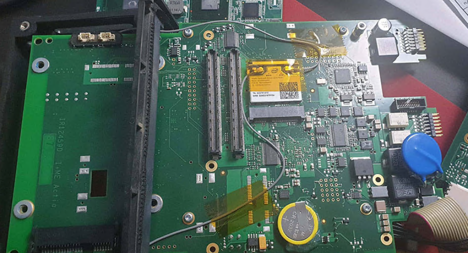
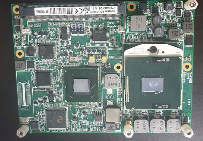
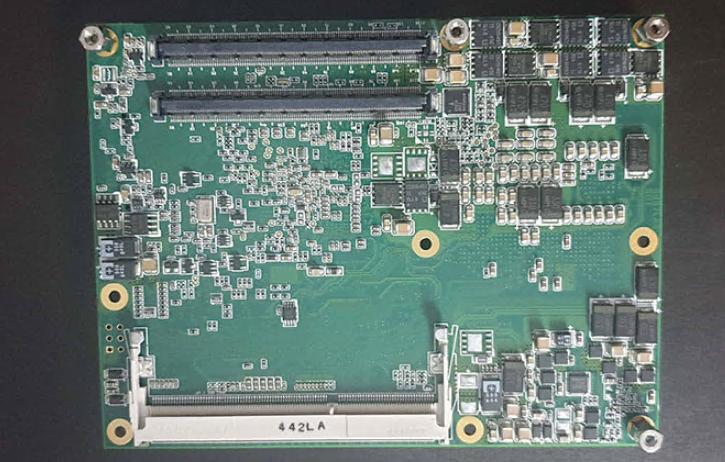
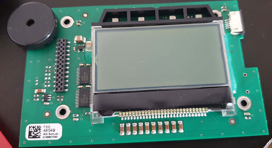
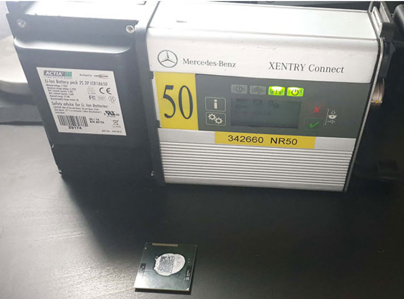
Well, after buying lots of Xentry Connect and working with them, I realized, man they are slow as shit, from booting up the interface, to appearing in xentry control, to opening up xentry, lots of time, this is because it is not like china clones, or SDConnect (C4), or VCI (C6) which are normal interfaces not a whole computer like Connect, so I managed to completely disassemble the interface and see if it is possible to do something about it.
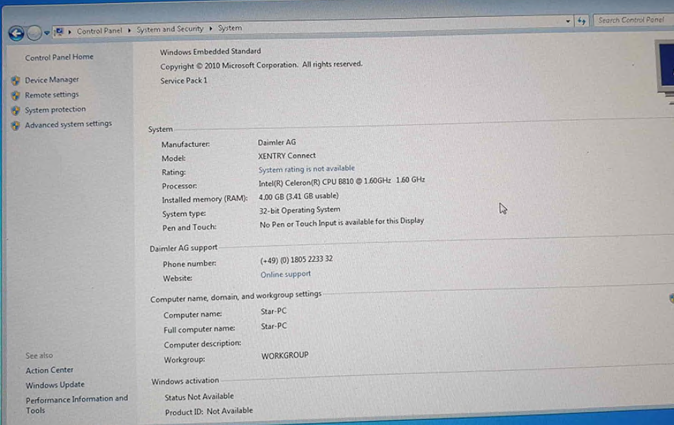
So, this interface or minicomputer has the following:
OS: Windows 7 32bit Embedded
MB: HM65 Chipset
CPU: Intel Celeron B810 2 cores 2 threads 1,6Ghz 35w, 2mb L3 cache,
PGA989 (2nd gen) this is the biggest issue, cheap shit processor
GPU: Integrated obviously
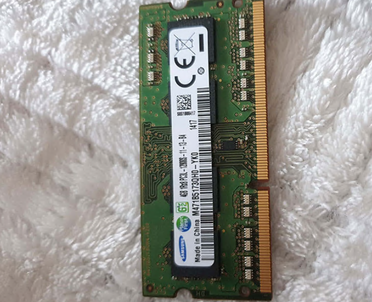
RAM: 4Gb Samsung DDR3 1333Mhz, can’t put 8gb because windows is 32bit so limited to 3,5Gb
SSD: Xmore quality 256GB
WiFi: Intel Centrino Advanced-N 6205 2,4Ghz and 5Ghz 300mbps PCIe Half MiniCard not wow but decent
it has a USB dongle into the board, it is 4Gb, no idea what this is
This device is in testing/development at least since 14/07/2011, first versions appeared in at least 2012
I encountered 2 versions of this ssd, 1 with 238GB found on XC older than 2014, 1 with 223GB found on XC newer than 2015
Upgrade: change that celeron cpu to something better, I personally changed it to i7 2640m 2 cores 4 threads 2,8Ghz 3,5Ghz 4Mb cache 35w
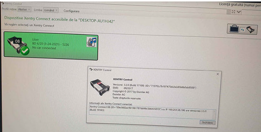
From starting xentry program until Data status 2020/06 appeared
Celeron: 57 Seconds
I7 2640m: 25 Seconds
From Sleep mode to No car connected
Celeron: 47 Seconds
I7 2640m: 37 Seconds
MUCH FASTER in Xentry program!!!
The reason why I choose the i7 2640m is because it is the most powerful
2nd gen processor of 35W (VERY IMPORTANT), more watts mean more heat,
and the interface only has 1 small radiator and 2 small ventilators
(like a laptop), i wouldn’t risk for right now putting a better
processor as i’m afraid it will not cool as it should, it will overheat
Tried a 2670qm (4 cores 8 threads) and the interface shuts down, not temperature problem but watt consumption problem, motherboard can’t deliver enough power and shuts down even ventilators completely, so maximum i recommend 2 cores 4 threads
Also, it is possible to install 3rd gen processors but motherboard doesn’t support 3rd gen processors even doe it is the same socket PGA-989
Check attachment regarding Compatible processors for 2nd gen
INSTALL:
1. Take out battery
2. Take out shield from Backside of Xentry Connect, it has double side addesive
3. Unscrew the 6 screws from radiator
4. Take out radiator
5. Turn the small black protection
6. Change cpu with NEW thermal paste
7. Put all back and that’s it
SSD: You could try putting a better ssd, space is
enough actually more than needed for only Xentry, it’s ok for Vediamo,
WIS/EPC, Monaco etc.
Couldn’t find any data or performance stats for this ssd, never heard
about this company, you can clone this ssd with another one and try
Ram: 4Gbs is max for 32bit, even more, no reason to put more than 4Gb ram, only if you somehow manage to install windows 7 embedded on 64bit
WiFi: Looked for the Intel AC-7260 but it is said it is buggy as hell, also you need to change drivers for the wifi card, which is kinda complicated, you can install driver booster on the interface’s windows (through remote desktop connection) and install driver from the wifi card you install
It supports USB 2.0, 3.0 and 3.1
SOFTWARE:
1.1 Xentry Tab (Part of Xentry Kit 2)
This is the software that you will have on your laptop
1.2 Options:
1)Download separately Xentry Tab from attachment you have there Setup, open and install
2)Skip to 2.1 and install from Xentry Kit 2 folder, you have there Setup, open and install
2.1 Xentry Connect (Part of Xentry Kit 2)
I highly recommend to update interface to latest Xentry, which is
2020.06 also there will not be a newer Xentry for this interface, need
to buy kit 3 or 4
1. Link is in the attachment, download KIT2 06-2020 Final Edition
2. Extract with 7zip and copy the folder and put it on a minimum 32Gb USB Stick or External SSD/HDD
3. Installing the release update on the XENTRY Connect
Please note: The XENTRY Connect must be in standby mode to install the release update. You can shut down the XENTRY
Connect directly on the device via the menu (gearwheels button) or from the XENTRY Control session.
4. Connect the power supply unit to the XENTRY Connect and insert the USB data storage medium into a free USB port of the XENTRY Connect.
5. Now start the update mode of the XENTRY Connect by simultaneously pressing the two “red cross” and “green tick”buttons.
6. Once “Start update” appears on the display, confirm this with the green tick. The update procedure starts. This will be indicated as follows on the XENTRY Connect display:
The USB update takes about 100 minutes. The XENTRY Connect indicates when the update is finished on the display.
7. You can complete the process by pressing the “gearwheels” button. Or, wait until the XENTRY Connect automatically shuts down (approx. 10 minutes after the picture appears on the display).
2.2 Configuration from Xentry Control
1. Start the interface
2. Connect LAN cable to interface and laptop
3. Open Xentry Control and in the top section open configuration
4. Go step by step with lan and wifi and others bla bla
2.3 Xentry License/StartKey
In case your Xentry Connect has expired license, 99% chance because
dealership started to use kit 3 from 2018/06, can check by opening
StartKey Center or Xentry (No Acces authorization code), then you need
to activate license
For this, i’m not publishing for free solution, contact me if needed, activation is 100 Euros
Problems/Issues/Errors:
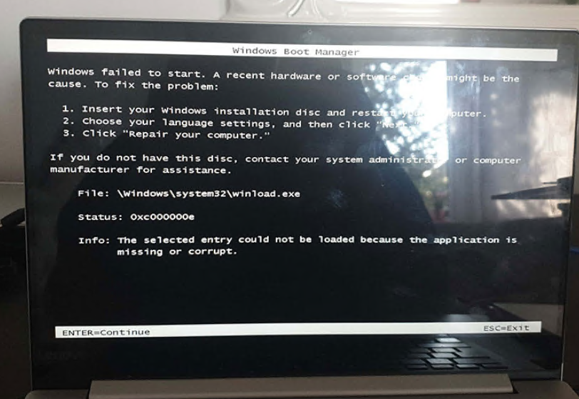
In case you have Device is booting/Update (when not updating) for looong time, more than 3 minutes
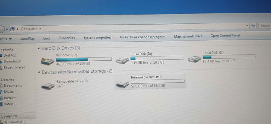
1. Make NORMAL not embedded Windows 7 32bit NOT 64bit USB bootable drive, minimum 4Gbs
In case you have new laptop with USB 3.0 and you have no mouse in Windows 7 install setup, you need to integrate USB 3.0 Drivers into Windows 7 ISO with NTLite, check youtube
2. Take out SSD from Xentry Connect
3. Connect to laptop, or if you have older laptop install in laptop
4. Connect USB Stick with Windows Embedded 7 32bit
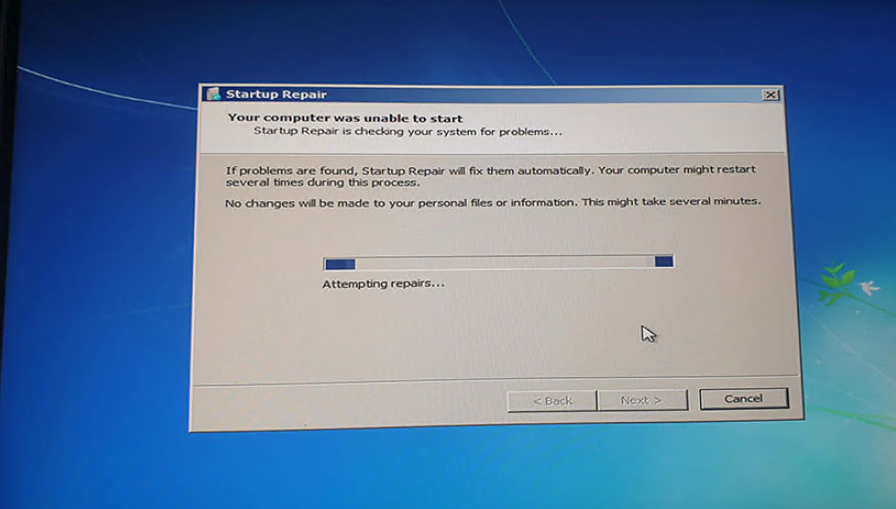
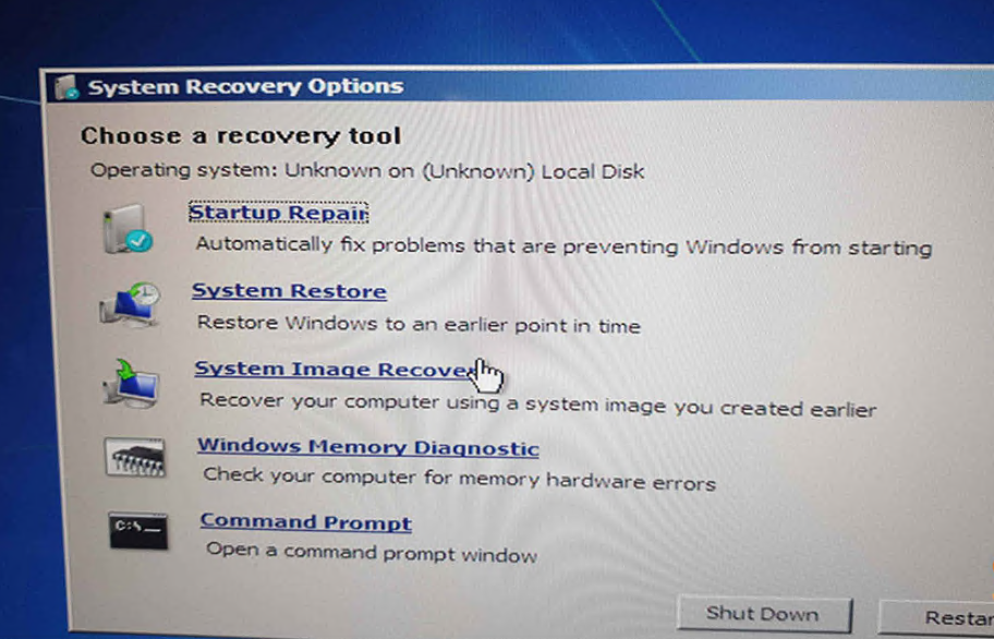
5. Select Language, Repair my computer
6. Select Startup Repair, let it do it’s thing
7. Insert SSD back to Xentry Connect and done
VERY IMPORTANT, PUT AT LEAST 1 SCREW to hold SSD to not move, if it moves you will corrupt BCD again (not booting, update/device is booting for long time, jump to 2)
If you have update error, doesn’t matter what error:
1. Open Support Tool
2. Go to Reset
3. Check I have spoken to the Diagnosis UHD and would like to reset the Xentry Connect
4. Click Setting up USB data media
5. Select USB stick (file that will be on USB stick is 1.6KB so insanely small)
6. Insert USB stick into XC
7. Press Tick (Green) and X (Red) at the same time (while in Sleep mode)
8. Let it to it’s Reset (x/15)
9. Perform Update with 2020/06
Only the display is lighting up but no text can be from multiple causes, internal defect, missing hardware display files, bios chip fucked etc.
If you don’t want to change cpu which would be a stupid decision, at least take off the back cover, A LOT of dust accumulated over the years can be there and it is blocking cooling very badly (see picture attached)
OPTIONALLY
DAS Standalone
Vediamo 05.01.01
WIS 2020.04 (after 2020.04 xentry connect no longer supported), i tried
copying missing files from 2020.04 to 2020.10 but it doesn’t work and
it’s not that simple)
DTS Monaco 8.16
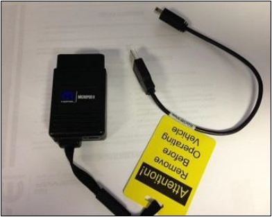
In order to ensure the wiTech MicroPod 2 is working properly, it will be necessary to update it based on the latest software releases provided by Chrysler. If your microPod is at version 0.4.2, it will not communicate with wiADVISOR. You must perform an update to version 1.2.2 using the USB cable that came with the microPod (see below).
To update your microPod using the USB cable:
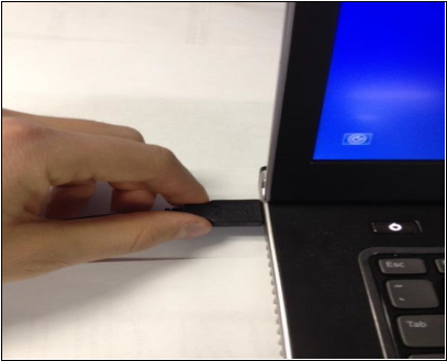
1.Connect the large end of the USB cable to a computer that has the wiTECH Diagnostic Application already installed – Typically this is a computer in the shop.
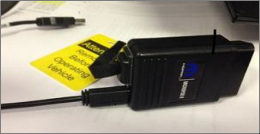
2.Connect the small end of the USB cable to the microPod as shown below:
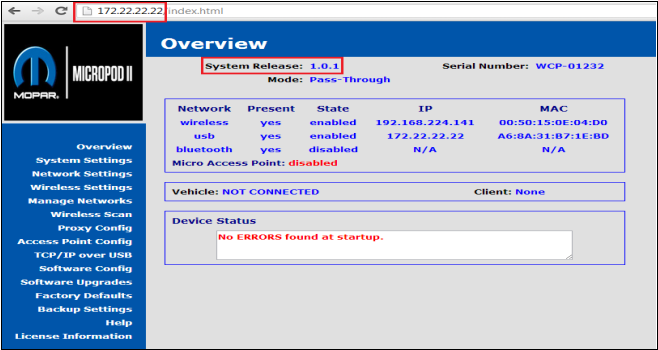
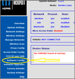
3.Once the microPod is connected via USB, a green light will come on. Open your Internet browser and type the IP address 172.22.22.22 in the address bar at the top of your browser and hit Enter on your keyboard. The microPod interface will come up as shown Below:
a.If the System Release shows any version besides 1.2.2 (red box on image above), then your microPod should update to the most current version if the wireless connection on the microPod is properly configured.
-OR-
b.If the System Release version shows 0.4.2, the wireless connection on the microPod must be configured in order for the microPod to update.
Once wireless is configured, simply wait until the light on the Auto Scanner Tool microPod will begin to flash with slow bursts of red indicating that the microPod has started the update process. You will not be able to access the microPod during the update and will have to wait 4-6 minutes before it finishes. The flashing red light will return to green once the update is complete.
4.NEXT: Click on ‘Software Config’ (left side):
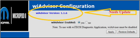
a.If the wiADVISOR version is 1.1.6, this needs an update. See below:
b.To update the App Version to 1.1.9, simply leave the microPod plugged into the PC. Pod will update itself. Refresh the screen until the version shows 1.1.9.
5.Now that your microPod System Release shows version 1.2.2, and the software shows an App version of 1.1.9, your microPod is now up-to-date.
Determining the Status of your microPod:
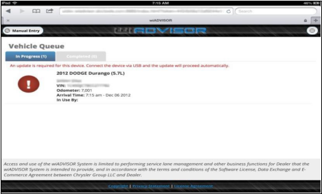
If you are not sure if your microPod requires an update, follow the below steps to confirm this. To view the current status of your microPod, you must be logged into the wiADVISOR application and have selected “Vehicle Queue” in the interface. When a microPod is powered up, the software status will be displayed along with connected vehicle information.
1.microPod Status Types – There are three types of update statuses available for the microPod:
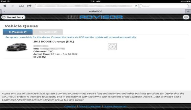
a.Up-to-date – This status indicates that your microPod is up-to-date and no further action is required at this time. If the software is up-to-date, no status information will be displayed. Otherwise one of the following two scenarios will be shown.
b.Update Available – This status indicates that there is an update available for your microPod. It is highly recommended that you update your microPod at your earliest convenience. You may continue to use the microPod without updating it when this status appears.
c.Update Required – This status indicates that an update is required on the microPod in order to continue using it.
2.To update the software, disconnect the microPod from the vehicle and connect it to your computer using the USB cable (computer must have the wiTECH Diagnostic Application installed).
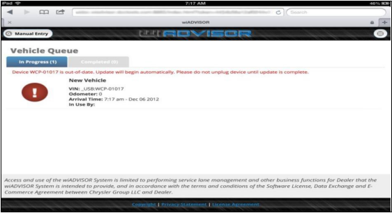
3.Since your microPod is updated to the 1.2.2 System Release; once booted and no vehicle power is detected, the microPod will automatically begin the update process. Depending on what software is being updated, the process can take anywhere from a few seconds to several minutes. During this time the LED lights will blink red and off. Monitor the Vehicle Queue to determine if the update has completed. Disconnecting the USB cable prior to update completion may leave the microPod in an irrecoverable failure state.
After powering up with the USB cable, the screen will warn you that
the update is starting and you must not unplug the device until the
update is complete (see below).
4.When the update is completed, the text in the Vehicle Queue will change indicating that microPod is up-to-date. At this time, it is safe to disconnect the USB cable and re-connect to a vehicle.
Troubleshooting Tips:
If you find that you are having issues with updating your wiADVISOR microPod there are few resolutions you can try.
1.Make sure you have wiTECH installed on the computer. (The microPod needs the wiTECH drivers in order to connect to the PC)
2.Try a different USB to mini USB cable.
3.Unplug the cable from the PC and try a different USB port.
4.Try a different PC; make sure you are in range of the wiADVISOR Access Point.
If you have any questions or concerns, please contact us via email at sales@obd2tool.com.
https://chryslertroublerepair.blogspot.com/2021/08/how-to-update-wiadvisor-micropod.html