This article show a guide on how to remove Ford Focus 2008 Launchbox exhaust resonaor.The “Lunchbox” in this case is the resonator at the end of the exhaust system closest to the exhaust tip.
What You Need?
18” (51mm) of Flexible Exhaust Pipe – 2” inside diameter
$5.99 AutoZone part #17033 – “Flexible Exhaust Repair Kit” is an 18”
piece of 2” I.D. flex pipe which includes (1) 2” Exhaust Clamp.
(1) 2” Exhaust Clamp
$2.49 AutoZone part #17124
(1) Exhaust Joint and Crack Seal
$2.99 AutoZone part #00160 (or exhaust seal/cement or your choice)
(1) spray can of Hi-Temp Paint
$5.49 AutoZone part #DE1634 Low Gloss Black Engine Enamel (use any hi-temp paint/color you want)
Tools Required:
Reciprocating Saw with metal cutting blade / hacksaw can be used (see note below)
3/8” and/or 1/2″ socket or box end wrench (to fit exhaust clamp nuts)
Sandpaper (pick a grit between 120 or lower, you’re just scuffing the pipe a little with it)
Manual or Hydraulic jack
Jack stand(s)
Wheel blocks
Instructions:
Locate vehicle on a solid level surface
Make sure it’s in PARK or 1st gear
Make sure the PARKING BRAKE is set and set good
Block front wheels
Now go back and make sure it’s in PARK or 1st and the PARKING BRAKE is set.
SAFETY FIRST: Allows use jacks stands when you are working under a
vehicle. Please DO NOT skimp on this, many a weekend warrior has died
when the car slipped off the jack.
Raise left rear to provide access to resonator (position jack correctly on vehicle to avoid damage)
Set Jack Stand(s) in place
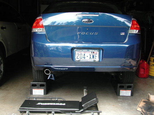
Note: Service ramps are a great time saver and I believe them to be much
safer than using an individual manual or hydraulic jack. For $39.99 you
can purchase a pair of 8000lb Rhino ramps at AutoZone. SAFETY FIRST:
Use Jack stands even with service ramps, look under my exhaust tip, you
can see one there and there is another one on the other side out of
view.
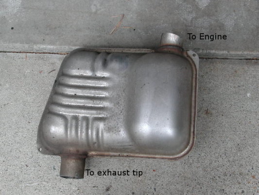
Remove Resonator
The resonator is the lunchbox looking thing welded to your exhaust tip
(sorry no picture of it in place, but see removed resonator picture
below).
Remove it!
Here’s a picture of mine after it was removed. The cuts I made worked out great for installing the flex pipe. You can adjust these cuts to suite your preference. Just remember “measure twice, cut once”.
Install Flex Pipe
Clean the outside of existing pipe where the flex pipe will overlap it,
about 2 inches should do. Also scuff this area with sandpaper to allow
for better adhesion of exhaust seal.
I wore rubber gloves for the next part, do not get this stuff all over your hands. It is labeled “WARNING! Eye, skin and respiratory irritant”.
Apply a liberal amount of exhaust seal to the outside of existing pipe (the area you just cleaned) and to the inside of the flex pipe before you slip the flex pipe on.
Slide flex pipe on, bending to position tip correctly. (fine tuning of tip position done later)
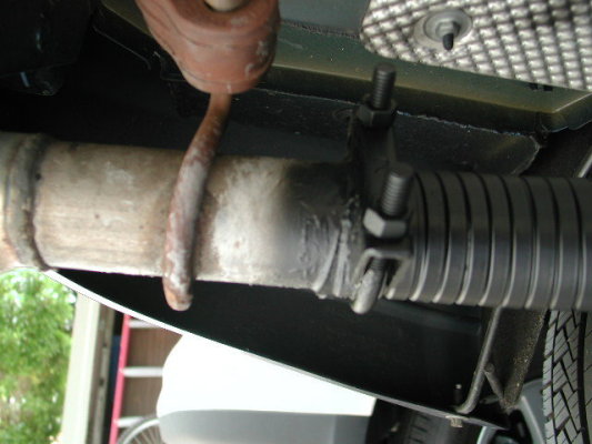
Now apply a liberal amount of exhaust seal over the end of the flex pipe and existing pipe; fill any gaps between the two. Use enough seal so you don’t even see the joint, basically blend the flex pipe into the existing pipe with the exhaust seal.
Install exhaust clamps (one on each end) and tighten. Position the ends of the clamp up toward the bottom of vehicle so you don’t see them sticking down when viewing the vehicle from the rear.
Check the exhaust seal after tightening clamps, add more if required.
Take a look at your exhaust tip (from behind the car), is it straight and centered? Adjust flex pipe until it is.
Except for painting you are done and you want to wait until after the exhaust seal is dry enough before you paint it. You could of course paint the flex pipe prior to installation, but I was not that smart.If you do paint prior to installing it you will still need to touch it up as areas that were not exposed on the flex pipe when you painted it will be now.
You can leave the car in position and wait, or carefully lower the vehicle and drive it. The heat from the exhaust will help set the exhaust seal. I painted mine after driving for about 10 minutes.
Yes, you do want to paint the flex pipe. Flex pipe is notorious for rusting quickly; the paint will help delay that process (a little). If this is a permanent addition you might do well by finding an exhaust shop that will bend and weld an actual piece of exhaust pipe in place at a reasonable price.
Also, if you move the flex pipe (or it moves on its own) after it’s painted it will expose unpainted areas. Watch for those and hit them with a spray of paint.
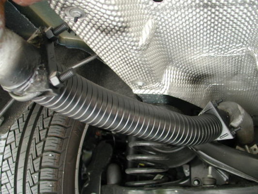
Below are pictures of my completed installation (including paint over spray on heat shield, oh well).
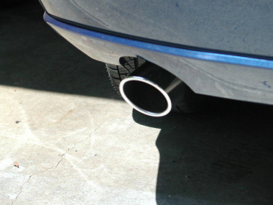
You better appreciate the shine on the tip. Took some time with bug and tar remover and steel wool followed by a waxing to get it looking good again all just for that picture.
Well that’s it; I hope you find these instructions helpful.